


Next: 2.3.1 Thermal Simulation
Up: 2. Circuit Equations
Previous: 2.2 Modified Nodal Approach
To be compatible with the constitutive relation formulation used for the transport equations
(
f(x) = 0) the constitutive relations for the device compact models are
formulated in the same way rather than directly calculating linearized circuit
elements. MINIMOS-NT solves for
f(x) = 0 using a
Newton algorithm:
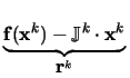
-  k . u k . u |
= |
f(xk) |
(2.18) |
| xk + 1 |
= |
xk + u |
(2.19) |
| k |
= |
 
 . . |
(2.20) |
This formulation has the advantage that the error in the sum of branch
currents is available as the residuum of the equations system at each
iteration. Furthermore, the implementation of non-linear constitutive relations is simpler
than deriving a linearized companion model. The original MNA formulation
can be related to the above formulation by
 . xk + 1 . xk + 1 |
= |
 . . |
(2.21) |
Equation (2.21) is of fundamental importance as it allows for
conversion between models implemented for SPICE into MINIMOS-NT models by
general purpose wrapper functions. Only the right hand side needs to be
modified to transform the values obtained from SPICE model call into the
stamps needed by MINIMOS-NT.
In MINIMOS-NT the constitutive relations for the node voltages are defined to be the sum of all
currents flowing into this node which must be zero. There is no
separation between passive elements and source terms. It is to note that the
opposite direction of current flow originates in (2.18) where the
negative derivatives are used to assemble the system matrix. This
definition is, of course, arbitrary, but defining the current direction this
way positive main-diagonal elements are obtained as in the conventional
formulation.
The constitutive relation for each node voltage is the sum of the device currents flowing into
the node.
Branch currents are normally introduced for voltage sources and ammeters. The
latter is a voltage source with zero branch voltage which introduces the
branch current into the system matrix so that it can be used to control
another element. The branch current constitutive relations state relationships
between node voltages, e.g.,
 -
-  = V0.
= V0.
Figure 2.3:
Currents and voltages for a device with N-terminals as used by MINIMOS-NT
![\begin{figure}
\begin{center}
\resizebox{7.8cm}{!}{
\psfrag{n-term}{\hspace*{-.7...
...ncludegraphics[width=7.8cm,angle=0]{figures/n-term.eps}}\end{center}\end{figure}](img89.gif) |
For an N-terminal device with B branch currents, one gets N + B device relations.
fd =  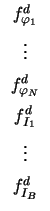
![$ \left.\vphantom{ \begin{array}{c}\vspace*{0.2cm} f^d_{\varphi_{1}} \\ \vspace...
...cm} f^d_{I_1} \\ \vspace*{0.2cm} \vdots \\ f^d_{I_B} \\ \end{array} }\right]$](img92.gif) =
=  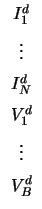
![$ \left.\vphantom{ \begin{array}{c}\vspace*{0.2cm} I^d_1 \\ \vspace*{0.2cm} \vd...
...pace*{0.2cm} V^d_1 \\ \vspace*{0.2cm} \vdots\\ V^d_B \\ \end{array} }\right]$](img95.gif) with with  Idn = 0 Idn = 0 |
(2.23) |
The partial contribution of the device d to the Jacobian matrix is given by
 d = d =  |
(2.24) |
where
xd contains all unknowns which control the device behavior.
Next: 2.3.1 Thermal Simulation
Up: 2. Circuit Equations
Previous: 2.2 Modified Nodal Approach
Tibor Grasser
1999-05-31