

Next: 4.4.2 Numerical Backward Transform
Up: 4.4 Numerical Implementation
Previous: 4.4 Numerical Implementation
4.4.1 ``Alias Free'' Forward
Transform
The basic idea is to decompose the mask transmission function t(x, y) into
elementary geometrical patterns. Triangles are best suited for this purpose
because any function t(x, y) consisting of polygonal-shaped, piecewise
constant transmission
areas can be triangulated and an analytical expression for the
Fourier coefficients of a triangular-shaped area can easily be derived
(cf. Appendix B.1). As a typical photomask often consists
of rectangular areas we consider them as the second type of elementary
patterns. Formulae for the Fourier coefficients of rectangles are presented in
Appendix B.2.
Let us now find a mathematical description for the proposed algorithm.
The area of a general elementary pattern is described by its indicator function
PAT(x, y) defined as
 |
(4.91) |
In our situation the elementary patterns are either triangles or rectangles.
In principle any other pattern type can be used as long as analytical
expressions for its Fourier coefficients can be derived.o
The decomposition of the mask transfer function formally writes as
 |
(4.92) |
whereby tk is the transmission of the respective elementary pattern.
In the case
of binary masks all transmissions tk equal unity, for phase-shifting
masks tk is a complex number with module less or equal one, i.e.,
 |
(4.93) |
Due to the linearity of the Fourier transform the
coefficients Tnm of the mask transmission function t(x, y) can
be computed as follows:p
The term in square brackets in the last row, i.e.,
 |
(4.95) |
can be calculated analytically for the elementary patterns
(cf. Appendix B) and the Fourier coefficients Tnm follow to
 |
(4.96) |
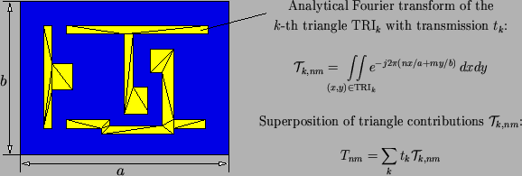
In Figure 4.10 the proposed procedure is demonstrated
for a simple triangulated mask pattern [128]. As mentioned before, the
algorithm
has the big advantage that the Fourier coefficients Tnm are calculated
exactly, i.e., no sampling of the mask transfer coefficients is involved.
A pertubation analysis of the analytical formulae shows that the formulae are
numerically robust (cf. Appendix B.3).
In addition to accuracy speed is the second important benefit.
The calculation is faster when compared to a numerical FFT transform,
because the formulae for
 k, nm can easily be evaluated
(cf. Appendix B). This second point is especially
important for a sparse layout as the mask can be decomposed into a relatively
small number of geometrical patterns.
Figure 4.10:
The
Fourier coefficients of the mask transmission function are computed
semi-analytically by decomposing the mask into elementary patterns,
calculating their coefficients analytically, and superposing these
contributions.
|
|
Footnotes
- ... derived.o
- The
Fourier coefficients of polygonal areas can always be computed analytically;
circular or elliptic areas can also be treated analytically.
- ... follows:p
- We assume here that the mask transmission
function is already scaled with the magnification M of the projection printing
system.


Next: 4.4.2 Numerical Backward Transform
Up: 4.4 Numerical Implementation
Previous: 4.4 Numerical Implementation
Heinrich Kirchauer, Institute for Microelectronics, TU Vienna
1998-04-17


![$\displaystyle = \frac{1}{ab}\int\limits_0^a\!\!\int\limits_0^b \left[\sum_k t_k \mathrm{PAT}_k(x,y)\right] e^{-j2\pi(nx/a+my/b)}\,dxdy$](img723.gif)
![$\displaystyle = \sum_k t_k \left[\frac{1}{ab} \int\limits_0^a\!\!\int\limits_0^b \mathrm{PAT}_k(x,y) e^{-j2\pi(nx/a+my/b)}\,dxdy \right].$](img724.gif)


