

Next: 4.2.1 Graphical User Interface
Up: 4 Implementation Issues
Previous: 4.1 Summary of the
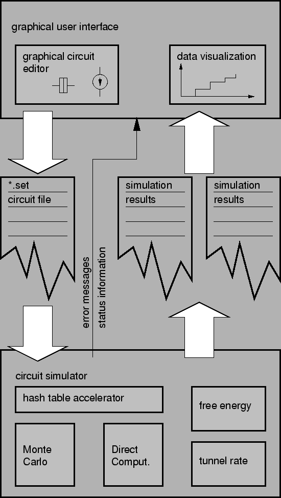
SIMON consists of two main blocks, the
graphical user
interface (GUI) written
in tcl/tk [57] [94] and the circuit simulator
written in ANSI-C [60]. The primary means of communication are
ASCII files
for the circuit description (*.set) and simulation results (*.set.i*,
*.set.u*, *.set.q*). The circuit simulator additionally communicates error and
status information to the GUI which informs the user about the simulation
progress. The decision to use ASCII files as the interface between GUI and
circuit simulator has two reasons. First we wanted to stay compatible with
text only systems. SIMON can fully be used with a text terminal.
Secondly, it nicely separates the two main parts and facilitates development.
In addition the usual ASCII files involved are not very large.
Fig. 4.1 shows the main building blocks of SIMON.
Figure 4.1:
The main building blocks of SIMON.

|
SIMON is capable of simulating an arbitrary connection of tunnel junctions,
capacitors, constant voltage sources, piece-wise linearly time dependent
voltage sources, and voltage controlled voltage sources. No principal
restrictions on the number of junctions or nodes exist. SIMON automatically
detects missing connections of circuit objects and short circuits of voltage
sources. Co-tunneling can be simulated
up to any order desired. However, the run time of the simulation grows
exponentially with the order of co-tunneling, which sets a practical limit.


Next: 4.2.1 Graphical User Interface
Up: 4 Implementation Issues
Previous: 4.1 Summary of the
Christoph Wasshuber
