« PreviousUpNext »Contents
Previous: 1.6 Failure Mechanisms in Interconnects Top: 1 Introduction Next: 1.8 Outline of this Thesis
1.7 Electromigration Induced Failures
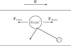
One of the processes leading to wear-out degeneration in interconnect structures is EM, the directed transport of atoms under the influence of an electric field acting as one force and a resulting electric current contributing to a second force. The electric field force- the so called direct force- is a result of the ionic character of atoms in a metallic lattice as the valance electrons responsible for the electric conductivity are not bound to their atom anymore. Furthermore, the conducting electrons driven by the electric field are scattered at the atoms exerting a force on them and this force is the so called wind force. Figure 1.6 depicts this circumstances.
Beside this phenomenon, other material transport inducing phenomena are acting inside metals. Some are uncorrelated to the EM induced flux, e.g., thermal migration [103], and some are compensating partially the EM flux [18], e.g., diffusion [32]. The transport of material in interconnect structures is leading to a mechanical stress build-up in the structures. These stresses can be tensile, when material is transported away, causing cracking or void formation and thereby leading to a degradation as the conducting cross sections are reduced. In the worst case an open circuit failure can be observed. The stress can also be compressive, which can crack the passivation and isolation layers between interconnects or other devices and cause the formation of a hillock. This leads to a reduction of the isolation gaps and thus degrades or even destroys the desired function of an IC. Therefore, ICs have to be checked against these phenomena [33]. For these assessment tests under accelerated test conditions are carried out and the results are extrapolated to normal operation conditions. An extrapolation of the data is only reasonable, if the phenomenon leading to degeneration under accelerated conditions is the same as under normal operation conditions. Therefore, these tests have to be designed very carefully. Typical accelerated conditions are increased electric current densities and elevated temperatures. These conditions can cause melting especially in big devices like TSVs and thereby renders an extrapolation impossible as another phenomenon was tested against [135]. Due to this and the long times needed for experimental tests, TCAD simulations are the method of choice to give designers a tool for pretesting or even testing.
« PreviousUpNext »ContentsPrevious: 1.6 Failure Mechanisms in Interconnects Top: 1 Introduction Next: 1.8 Outline of this Thesis