 |
In the general three-dimensional case the structuring element is an ellipsoid
with the three diameters ![]() ,
, ![]() , and
, and ![]() . Its orientation is specified
by a polar and an azimuthal angle.
This general ellipsoid can be used to model reactive ion etching and sputter
deposition where the local rate depends on the visibility conditions
and is calculated as integral of the particle distribution function over
the visible solid angle.
. Its orientation is specified
by a polar and an azimuthal angle.
This general ellipsoid can be used to model reactive ion etching and sputter
deposition where the local rate depends on the visibility conditions
and is calculated as integral of the particle distribution function over
the visible solid angle.
For simple anisotropic models, the main axis of the ellipsoid is fixed to a
vertical direction and its size is given by a vertical rate ![]() and a lateral
rate
and a lateral
rate ![]() . For the isotropic case all three diameters are equal
. For the isotropic case all three diameters are equal ![]() ,
the ellipsoid merges to a sphere, and the orientation becomes insignificant.
,
the ellipsoid merges to a sphere, and the orientation becomes insignificant.
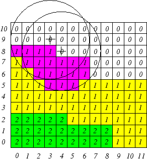
Deposition and etching is modeled in the same way, the difference is that for deposition vacuum cells hit by the structuring element are set to the index of the deposited material whereas for etching marked material cells are removed by setting them to the vacuum index 0. In this sense Fig. 2 shows the two-dimensional equivalent of circles modeling an isotropic process. The purple squares denote material cells hit by the structuring element which will be etched away in this time step.
As can already be seen in Fig. 2, the morphological operations cause
unnecessary and redundant operations. Unnecessary operations are performed
for the vacuum cells above the surface for etching processes and vice versa
for deposition. Redundancy originates from structuring elements applied to
adjacent surface cells hitting one and the same cell several times.
For larger simulation domains this turns out to be slow because of
the dependence of the calculation time on the number of cells.
If ![]() is the number of cells per micron, the number of operations on the
three-dimensional material array depends on
is the number of cells per micron, the number of operations on the
three-dimensional material array depends on ![]() . The same applies for the
scanning operation of the region surrounding the structuring element
when deciding whether a cell is inside the sphere or outside.
The calculation time of this second operation additionally increases with the
deposition rate
. The same applies for the
scanning operation of the region surrounding the structuring element
when deciding whether a cell is inside the sphere or outside.
The calculation time of this second operation additionally increases with the
deposition rate ![]() , because the rate determines the radius of the sphere and
thus the volume to be scanned.
, because the rate determines the radius of the sphere and
thus the volume to be scanned.
Our efforts to reduce such unnecessary and redundant operations and thus to increase the simulation speed for several etching and deposition processes are described in the next sections.