We discussed the governing physical equations which can be treated by PROMIS in Section 3.1 and applied these equations for diffusion modeling in Section 3.2. Now in the following sections we explain how these model equations are solved numerically in two-dimensional nonplanar domains. For those who are interested how the PROMIS Diffusion Module works internally here is exactly the right place to look for, for those who are not, just skip the next few sections and continue at the applications (Section 3.7).
The numerical solutions to partial differential equations are approximations
that usually depend upon some finite collection of points that cover the
domain on which the solution is sought. For solving partial differential
equations numerically we divide the simulation space into small elements
defined by a grid. A grid requires both, the points and neighbor
relations to the other points. This is in contrast to the our analytical
simulation method for ion implantation, there only the points were required
(cf. page  ).
).
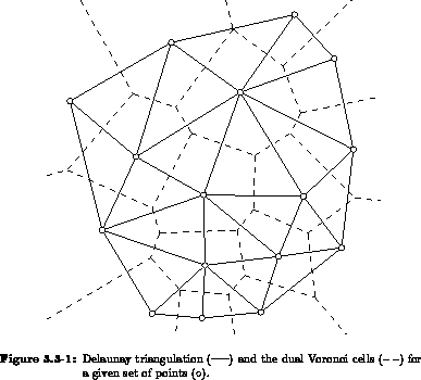
Every point in a set of points has a unique cell around it defined by the points which are closer to it than to any other point in the set. This cellular decomposition is known as the Voronoi tesselation and its dual grid is called the Delaunay grid [Pre85]. While Voronoi cells do not provide a connectivity graph between the original set of points, the associated Delaunay grid does (Figure 3.3-1). This Delaunay grid is always uniquely defined for an arbitrary set of points, however, it might lead to some undesired intersections with the given boundaries.
There is no real obligation to design grids based on the Voronoi construction. The connectivity pattern between the points is typically adjusted either to adapt more closely to the geometry or to accommodate a particular solution algorithm. In conjunction with, for instance finite element methods, there are many grid generators that do not employ Voronoi concepts at all. From a general perspective, the construction and use of any arbitrary set of points presents the most flexible format for adjusting to complex configurations and solutions. On the other hand, many of the best and most efficient solution techniques are either greatly weakened or are unavailable with such unstructured grids, see for instance [Poo87].
At the other extreme, there are the coordinate grids for which most of the efficient solution techniques are available. The most highly structured grid is the tensor product (or cartesian) grid. At a basic level, the connectivity is evident in terms of simply knowing the nearest neighbors to any given grid point. Unfortunately, tensor product grids are not flexible enough to deal with generally curved boundaries.
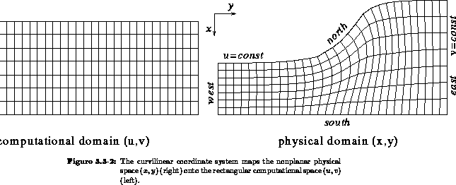
To preserve the connectivity structure of tensor product grids for regions with curved boundaries, coordinate transformations are employed. The tensor product grid is mapped onto a physical space grid so that the boundaries of the physical region are presented by discrete coordinate curves. In the mapping process, the connectivity of the tensor product structure is fully preserved, while the orthogonality can only be retained approximately.
We interpret the boundary fitted grid as a coordinate transformation from
a physical domain  to a computational domain
  . In the
computational domain the geometry appears as a rectangle. We find
the solution
. In the
computational domain the geometry appears as a rectangle. We find
the solution  to our problem (i.e. of the partial differential equations)
in the computational domain, rather than in the physical domain. Of course,
we have to transform the governing differential equations from cartesian
coordinates to our general curvilinear system .
to our problem (i.e. of the partial differential equations)
in the computational domain, rather than in the physical domain. Of course,
we have to transform the governing differential equations from cartesian
coordinates to our general curvilinear system .
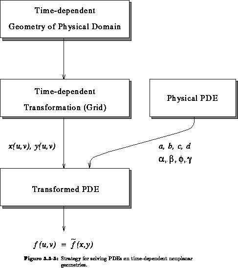
In process modeling we also have to deal with moving boundary problems where the geometry changes with time, e.g. during oxidation. With the transformation method the moving grid points in the physical domain are mapped onto fixed grid points in the computational domain. A consistent transformation of time derivatives in the physical equations allows us to perform all computations on the fixed computational grid without any interpolation, even though the grid points are in motion in physical space.
The transformed equations are unambiguously defined by the coefficients
 ,
,  ,
,  ,
,  ,
,  ,
,
 ,
,  , and
, and  of the physical equations
(3.1-1) - (3.1-3). In Section 3.3.5 you
will find the transformed model equations (3.3-61) -
(3.3-65). These equations together with the above stated
coefficients will be solved in the computational domain (see Figure 3.3-3
of the physical equations
(3.1-1) - (3.1-3). In Section 3.3.5 you
will find the transformed model equations (3.3-61) -
(3.3-65). These equations together with the above stated
coefficients will be solved in the computational domain (see Figure 3.3-3
In this section we describe the details of the transformation method which
is applied for the numerical solution of the model equations in nonplanar
structures. First, in Section 3.3.1 we explain the reference
mapping strategy which is a decoupling of the grid used to establish the
mapping from the physical domain  to the computational domain
  and
vice versa, from the grid used for the solution of the model equations.
Then, in Section 3.3.2, we will introduce just enough
differential geometric notation which is necessary to formulate fundamental
properties of the transformation clearly and concisely. We give an overview
of implemented grid generation methods in Section 3.3.3. The
remaining sections deal with transformation relations for the differential
operators (Section 3.3.4) and the model equations
(Section 3.3.5).
and
vice versa, from the grid used for the solution of the model equations.
Then, in Section 3.3.2, we will introduce just enough
differential geometric notation which is necessary to formulate fundamental
properties of the transformation clearly and concisely. We give an overview
of implemented grid generation methods in Section 3.3.3. The
remaining sections deal with transformation relations for the differential
operators (Section 3.3.4) and the model equations
(Section 3.3.5).