Charge Trapping and Variability in CMOS Technologiesat Cryogenic Temperatures
5.3 Characterization of SmartArray Structures
The first generation of imec-built SmartArrays was developed in 2013 [215]. Since then, almost every year an updated version of the chip has been designed and taped out using different technology nodes, geometries, doping profiles, etc. [216, 217, 218, 219, MJC3]. An overview of the different generations can be seen in Fig. 5.2. For this work, the designs from 2017 [MJC3] and from 2018 are used.
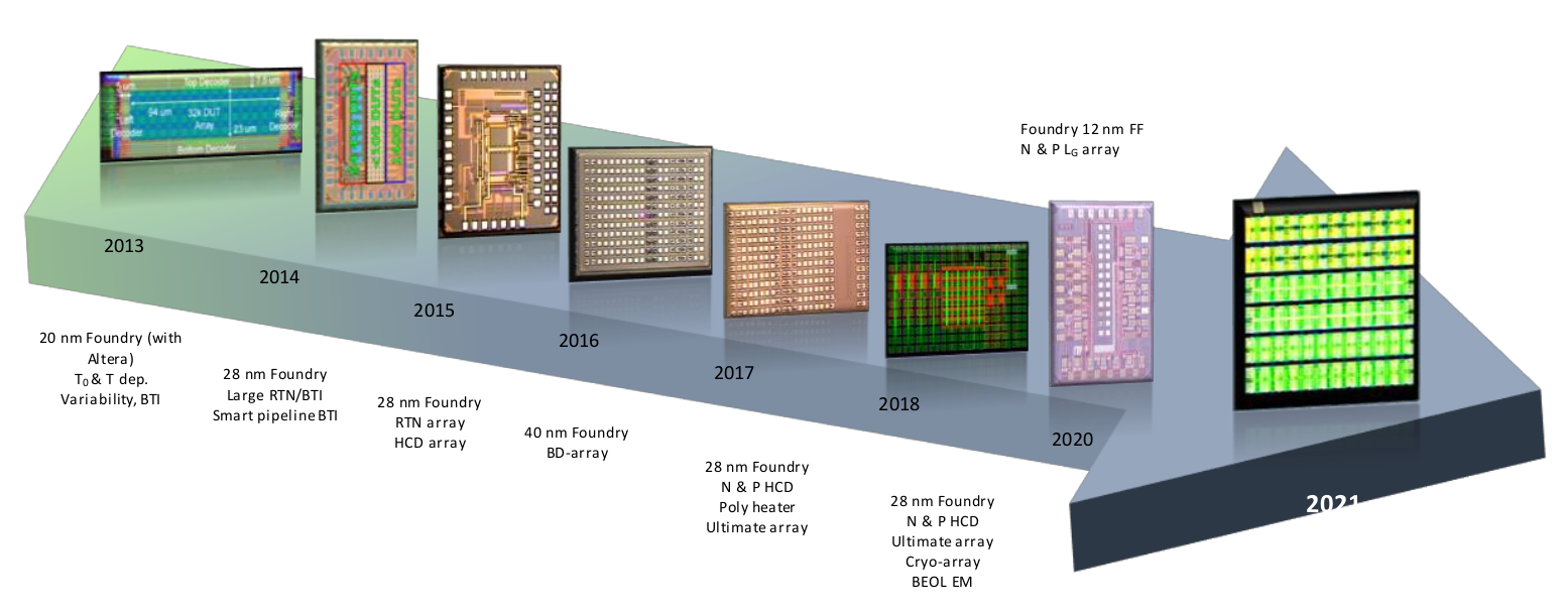
Figure 5.2: After the first generation of SmartArrays taped out in 2013 [215] containing 32000 commerically available devices fabricated within a 20 nm technology node, almost every year an updated version with different devices, doping, geometries, etc. has been designed [216, 217, 218, 219, MJC3].
SmartArrays have several advantages compared to measurements at single devices where the devices have to be contacted manually in order to collect a statistical relevant amount of data for a certain technology. The array structures are mounted and bonded onto custom-built PCBs, which avoids the need of probes and allows to sweep over the whole temperature range within one measurement without having the problem of mechanical tension of the probes on the metal pads on the wafer chip. Furthermore, it reduces condensation and contacting issues which regularly occur during manual operation. However, the main advantage is the availability of thousands of transistors which can be addressed individually using shift registers. The circuit topologies of the 2017 design of the SmartArray can be seen in Fig. 5.3.

The 2017 tape-out consists of twelve blocks with either 2560 nMOS or pMOS transistors of Tech. A each, with dimensions  which can be addressed individually. Each block has 256 gate lines, which can be selected digitally via shift registers and latches and ten drain lines, which can be connected to the ten SMUs available in the
custom-designed measurement tool. In the following sections, this tape out will be referred to as SmartArray A.
which can be addressed individually. Each block has 256 gate lines, which can be selected digitally via shift registers and latches and ten drain lines, which can be connected to the ten SMUs available in the
custom-designed measurement tool. In the following sections, this tape out will be referred to as SmartArray A.

Figure 5.4: The circuit topology of the SmartArray tape-out from 2018 (left) shows how 2500 devices can be addressed via ten drain lines and 250 gate lines. This can be done using a shift register. The devices
are organized in five blocks with 500 devices each, having different lengths values  nm. The SmartArray is mounted and bonded on a PCB (right) which allows to connect the array to a breakout box providing BNC connectors.
The 2018 tape-out is produced in two different flavors, nMOS and pMOS of Tech. A and will be referred to as SmartArray
B in the following sections. One SmartArray contains 2500 transistors of one MOS type, see Fig. 5.4 (left). Five different geometries are available, with 500 transistors per geometry. The available devices exhibit nm. The first 50 drain lines allow the selection of 500 devices of the smallest geometry using ten gate lines. The next 50 drain lines correspond to the second smallest geometry and so on. To characterize the array it is
encapsulated as shown in Fig. 5.4 (right) and bonded to a PCB. This allows to connect the pads to a breakout board in order
to interface the bonded SmartArray in the cooled vacuum chamber to the measurement equipment at room temperature. The measurement equipment presented in this chapter has been used to measure time-zero
characteristics and variability measurements which are shown in Chapter 6, charge noise characteristics presented in Chapter 7 and BTI characteristics discussed in Chapter 8.