Both the SHE and RE have been shown to be possible contributors to the SOTs in NM/FM bilayer systems. Both effects generate a spin polarization along \(\bm {E}\times \bm {z}\), which results in both DL and FL torques.
The SHE generates a predominantly DL torque, while the RE produces a strong FL torque. In experimental systems, however, it is challenging to separate the two effects and determine their relative contributions to the SOTs as
both are captured by the same measurements. Since the SHE is a bulk effect and the RE is an interfacial effect, they are expected to exhibit different dependencies on the NM layer thickness, providing some insight into their
relative contributions. To investigate this, the thickness dependence of the SOTs in various bilayer systems is computed using the 1D-CSDD model with the BCs derived in chapter 5 and analyzed. The interface parameters are then used as fitting parameters to reproduce experimental data from various bilayer systems, enabling reasonable
estimates of their values.
7.2.1 Bulk and Interface Contributions to SOTs
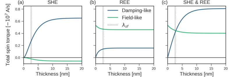
Figure 7.8: The dependence of the total torque on the NM thickness in a NM/FM bilayer system for SHE (a), RE (b), and a combination of SHE and RE generated torques (c). The results were obtained with the 1D-CSDD solver
with the IMR-BCs using the bulk and interface parameters presented in Tables 6.1 and 7.1,
respectively, except for \(u_R = 0.01\). A constant electrical field of \(10^{6}\, \mathrm {V/m}\) is applied along \(x\) and the magnetization is oriented along \(z\).
To investigate the thickness dependence of the SOTs generated by the SHE and RE, the total torque acting on the FM layer in a NM(\(t_\mathrm {NM}\))/FM(\(5\,\mathrm {nm}\)) bilayer system is computed for varying
thicknesses of the NM layer, \(t_\mathrm {NM}\), for each effect and the combination of both. To ensure that the SHE and RE torques are similar in magnitude, the Rashba coupling strength is set to \(u_R = 0.01\).
Figure 7.8 shows the resulting torques.
Both components of the SHE-generated torque disappear in the limit of zero thickness, and increase with increasing NM thickness until they reach a saturation level determined by the spin-flip length, a well-established result in the
literature [70, 76]. As the NM thickness increases, so does the current flowing through it and the resulting SHE-generated spin current. For thicknesses beyond the spin-flip length, part of the net spin generated is lost through
spin-flip scattering. The net spin generated beyond \(\approx 2\lambda _{sf}\) away from the interface entirely loses its spin polarization before reaching the FM. Thus, for larger thicknesses, the additional spin current does not
contribute to the torque, hence it saturates. The FL torque is generated by spin-flip scattering at the interface, captured by the mixing conductance. Therefore, the ratio of DL to FL torque is roughly determined by the ratio of the
real and imaginary parts of the spin-mixing conductance, respectively.
In contrast, for the RE, only the DL torque vanishes in the limit of zero thickness, while the FL torque increases. Both components saturate for thicknesses larger than the spin-flip length, remaining constant for larger thicknesses.
The increase in the FL torque is mainly caused by the SOP current on the NM side of the interface, which, for thicknesses below the spin-flip length, reaches the external boundary of the NM layer where it is reflected back towards
the FM, resulting in an additional contribution to the FL torque. Similarly, the SOF current on the NM side is also reflected back; however, it has an opposite polarization direction compared to the SOF current in the FM.
Consequently, it leads to an increasing reduction of the DL torque, until the reflected SOF spin current cancels out the one in the FM. The reason the RE torque saturates around \(\approx \lambda _{sf} \) and not \(\approx
2\lambda _{sf}\) as in the SHE case, is therefore that the SOP and SOF currents, which are reflected, must cross the NM layer twice before reaching the FM.
When both effects are included, the torque is characterized by a DL and FL component that vanish and increase with decreasing thickness, respectively, and saturate beyond a certain thickness. Thus, in the thick NM limit, the DL
torque is dominating, while in the thin NM limit, the FL torque is dominating. This behavior has been observed in various experimental systems [95, 96, 97, 98]. Although both effects contribute to both components, the DL
component can be predominantly attributed to the SHE, while the FL component can be predominantly attributed to the RE, due to their respective magnitudes and saturation thicknesses.
7.2.2 Comparison with Experimental Data
To investigate the Rashba SOC contribution to the SOTs acting on the FM layer in a real NM/FM bilayer system, the computed SOTs are compared to experimental data. Measurements of DL and FL SOTs for several Ir-layer
thicknesses in an Ir(\(t_{\mathrm {Ir}}\))/ CoFeB(\(2.3\,\mathrm {nm}\)) bilayer structure were reported in [98]. The experimental data show that the DL component increases with increasing Ir thickness, while the FL
component does not vanish with decreasing Ir thickness, which agrees qualitatively with the behavior observed in the previous section when combining the SHE and RE. In order to directly compare the computed torques with the
experimental data, they need to be converted into effective spin torque conductivities [98]:
\(\seteqnumber{1}{7.1}{0}\)
\begin{align}
\sigma ^\mathrm {eff}_\mathrm {DL} & = \frac {2e}{\hbar }\mu _0 M_s t_\mathrm {FM} \frac {H_\mathrm {DL} }{E}, \\ \sigma ^\mathrm {eff}_\mathrm {FL} & = \frac {2e}{\hbar }\mu _0 M_s
t_\mathrm {FM} \frac {H_\mathrm {FL} }{E},
\end{align}
where \(H_\mathrm {DL}\) and \(H_\mathrm {FL}\) are the effective fields corresponding to the DL and FL torques. The effective torque fields are related to the total torques acting on the FM layer as follows:
\(\seteqnumber{1}{7.2}{0}\)
\begin{align}
\bm {m}\times \bm {H_\mathrm {DL}} & = \frac {1}{\gamma _0 M_S}\bm {T_\mathrm {DL}}, \\ \bm {m}\times \bm {H_\mathrm {FL}} & = \frac {1}{\gamma _0 M_S}\bm {T_\mathrm {FL}},
\end{align}
where \(\bm {T_\mathrm {DL}}\) and \(\bm {T_\mathrm {FL}}\) are the total DL and FL torques, respectively.
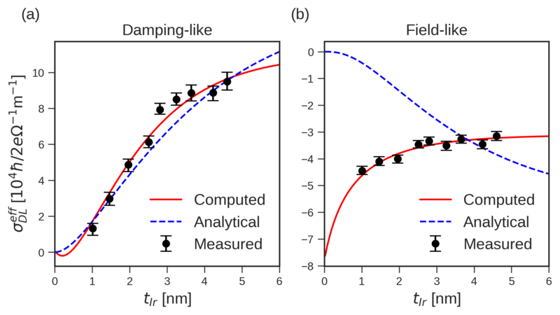
Figure 7.9: The Ir thickness dependence of the DL (a) and FL (b) effective spin torque conductivities for an Ir(\(t_\mathrm {Ir}\))/CoFeB(\(2.3\,\mathrm {nm}\)) bilayer structure with an in-plane current and magnetization
along \(x\). The experimental data was taken from [98]. The dashed lines show the best fit obtained using the analytical solution from Appendix B,
while the solid lines show the best fit obtained with the 1D-CSDD using the IMR-BCs.
Figure 7.9 shows the experimental data for the thickness dependence of the spin torque conductivities for Ir(\(t_{Ir}\))/ CoFeB(\(2.3\,\mathrm {nm}\)),
together with the best fits obtained using the analytical solution from Appendix B, and the 1D-CSDD solver with the IMR-BCs. A constant electrical
field of \(10^{6}\,\mathrm {V/m}\) was used for the computation, with both the magnetization and the electric field oriented along \(x\), and the interface normal is along \(z\). The CoFeB material parameters used are
presented in Table 7.2. For Ir, the conductivity \(1.4\,\mathrm {MS/m}\) and spin-flip length \(1.4\,\mathrm {nm}\) reported by Ref. [98] is used. The spin Hall angle
is set to \(\alpha _\mathrm {SHA} =0.02\) as reported by Ref. [99]. The best fit for the computed torques was achieved with the following interface parameters: \(u_0 = 0.326, u_m = -0.009, u_R = -0.006\), and
\(k_F = 10\,\si {nm}^{-1}\), while for the analytical solution the best fit was achieved with \(G^{\uparrow \downarrow } = (1.22-i0.84)\times 10^{14}\,\si {S/m^2}\) using \(\lambda _{sf} = 2.6\,\si {nm}\).
The analytical fit explains the DL torque well, yet it fails to reproduce the FL torque, which is expected, as it does not include interfacial SOC. The strong FL torque in the thick Ir limit can be accounted for by a large imaginary part
of the spin-mixing conductance; however, the non-vanishing FL torque in the thin Ir limit cannot be captured. In contrast, the 1D-CSDD model with the IMR-BCs reproduces both components of the torque accurately, suggesting
that both the SHE and RE contribute significantly to the SOTs in this system. This shows that the interfacial SOC plays an important role in generating SOTs in NM/FM bilayer systems, which is often overlooked in the typical
spin drift-diffusion models used to interpret the experiments. Interestingly, the fitted Rashba coupling strength has the opposite sign to the spin Hall angle, resulting in an opposite sign for the FL torque compared to the DL torque.
7.2.3 Rashba Interface Conductivities
Simulating magnetization dynamics with realistic SOTs requires including the interfacial SOC at the interface. However, using the IMR-BCs with the FEM solver is computationally expensive as the Fermi surface integrals must be
evaluated at every node in the effective interface layer and at every time step. Moreover, it is challenging to obtain accurate interface parameters through fitting the experimental data, as a change in one parameter affects both
components of the torque. Hence, it is more practical to use the IRPT-BCs, as the interface conductances and conductivities have a simple magnetization dependence that can be easily included in the FEM solver. Furthermore, to
capture realistic SOTs, the conductance and conductivities can be treated as fitting parameters, which allows for good fits to be obtained more easily, as they are directly related to the two torque components.
To obtain reasonable interface conductances and conductivities to use in later simulations, the thickness dependence of the SOTs is computed for Pt/CoFeB and W/CoFeB bilayer systems. These bilayer systems have been widely
studied experimentally, and the thickness dependence of the Pt/CoFeB and W/CoFeB SOTs has been reported in [100] and [101], respectively. Both Pt and W are HMs exhibiting large spin Hall angles and are thus often used as
the spin current source in SOT switching systems in combination with CoFeB FLs. Thus, the bilayer torques from these systems are the most representative of typical SOTs that are considered for SOT-MRAM applications.
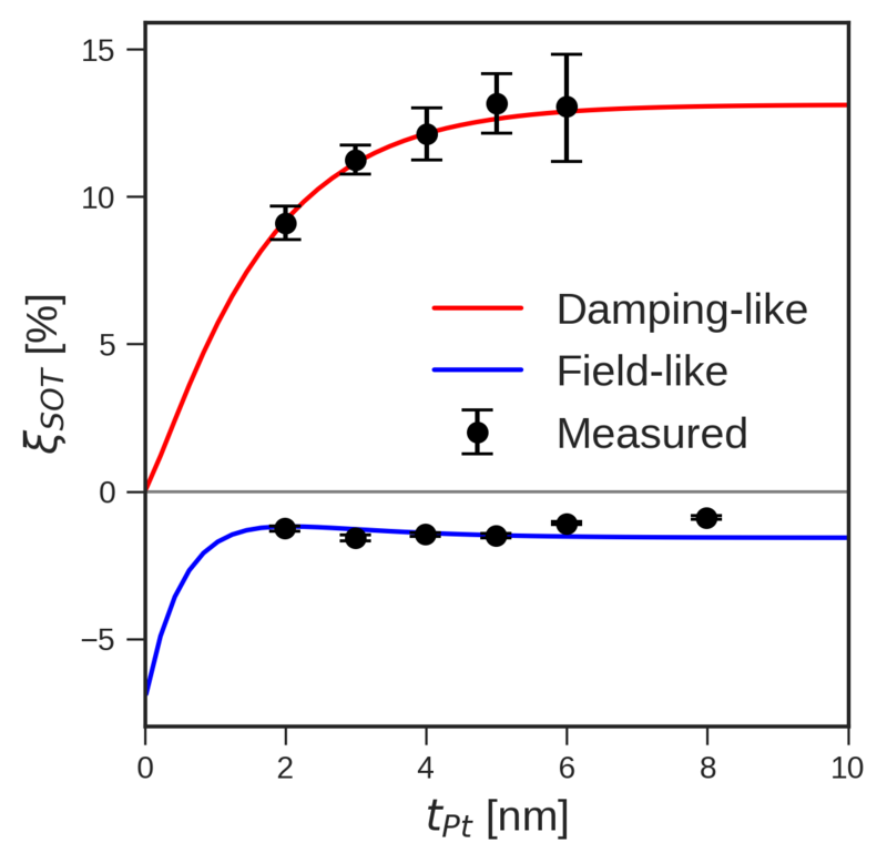
Figure 7.10: Thickness dependence of the Pt(\(t_{Pt}\))/CoFeB(3 nm)/MgO(1 nm) DL (a) and FL (b) spin torque efficiencies. The experimental data were taken from [100]. The fit was achieved using the 1D-CSDD solver
with the IRPT-BCs using the bulk and interface parameters presented in Tables 7.2 and 7.3.
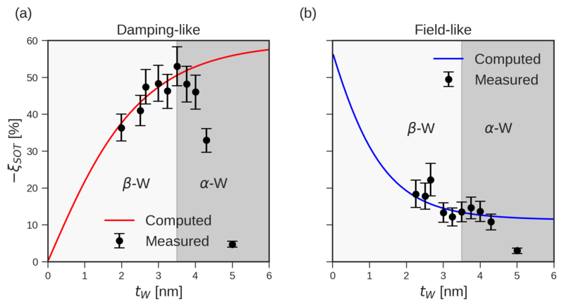
Figure 7.11: Thickness dependence of the W(\(t_{W}\))/CoFeB(1 nm)/MgO(1 nm) DL (a) and FL (b) spin torque efficiencies. The experimental data were taken from [101]. The fit was achieved using the 1D-CSDD solver
with the IRPT-BCs using the bulk and interface parameters presented in Tables 7.2 and 7.3. The dark gray region
indicates the \(\alpha \)-phase of W, which is not considered in the fitting.
.
Parameter
Pt
W
CoFeB
Units
\(\sigma \)
\(7\,\)
\(0.721\,\)
\(3.3\,\)
\(\mathrm {MSm^{-1}}\)
\(\alpha _\mathrm {SH}\)
\(0.19\)
\(-0.60\,\)
1
\(\beta _\sigma \)
\(0.56\,\)
1
\(\beta _D\)
\(0.7\,\)
1
\(\lambda _\mathrm {sf}\)
\(1.4\,\)
\(1.6\,\)
\(12\,\)
nm
\(\lambda _{J}\)
\(0.1\,\)
nm
\(\lambda _{\phi }\)
\(1.2\,\)
nm
Table 7.2: Bulk material parameters used for the fitting of the bilayer SOT dependence on the NM thickness. The bulk Pt parameters were taken from [102]. The W conductivity
was taken from [101], while the rest were modified to obtain a better fit while still staying consistent with the literature. The CoFeB conductivity and conductivity polarization were directly taken from [103], the spin-flip length was
estimated using equation (18) from Piraux et al. [104], using the data from [103], the remaining parameters were based on typical FM values encountered in the literature.
.
Parameter
Pt/CoFeB
W/CoFeB
Units
\(G^{\uparrow \downarrow }\)
\(2.0 + 0.70i\)
\(0.40 + 0.20i\)
\(\si {PSm^{-2}}\)
\(\sigma _R^{\uparrow \downarrow }\)
\(-0.81 + 0.70i\)
\(-0.91 + 0.13i\)
\(\si {MSm^{-1}}\)
\(\gamma _R^{\uparrow \downarrow }\)
\(-0.31\)
\(-0.50\)
\(\si {MSm^{-1}}\)
Table 7.3: Interface parameters for the Pt/CoFeB and W/CoFeB systems. The real part of the spin-mixing conductances was taken from [105] and [106], for Pt/CoFeB and W/CoFeB,
respectively.
The thickness dependence of the DL and FL spin torque efficiencies for
Pt(\(t_{Pt}\))/CoFeB(\(3\,\mathrm {nm}\))/MgO(\(1\,\mathrm {nm}\)) and W(\(t_{W}\))/CoFeB(\(1\,\mathrm {nm}\))/MgO(\(1\,\mathrm {nm}\)) bilayer systems are shown in Figures 7.10 and 7.11, respectively. The data for the FL torque in W/CoFeB was renormalized to the current
flowing through the SOT layer to be directly comparable with the DL torque measurements. The spin torque efficiencies are defined as
where \(\sigma ^{NM}\) is the conductivity of the NM layer. The bulk parameters used for W, Pt, and CoFeB are presented in Table 7.2. W transitions from its \(\beta
\) to \(\alpha \) crystal phase around \(t_W \approx 3.5\,\si {nm}\), since the \(\alpha \)-phase has a much lower spin Hall angle only the data from the \(\beta \)-phase is considered in the fitting. The best fit was
obtained with the interface parameters presented in Table 7.3.
The Pt/CoFeB reaches a torque efficiency of \(\approx 12\%\) for the DL component, while the W/CoFeB system reaches a DL torque efficiency of \(\approx -50\%\) when the W is still in its \(\beta \)-phase. The sign of the
DL torque efficiency is determined by the spin Hall angle, which is negative for W and positive for Pt. Although W is more efficient at generating SOTs, it has a high resistivity of \(138.7\,\si {\mu \Omega cm}\) compared to Pt
with \(14.3\,\si {\mu \Omega cm}\), which results in a much larger power consumption for the same current density. \(\alpha \)-W has a much lower resistivity of \(5-20\, \mu \Omega \si {cm}\) [101]; however, the spin
torque efficiency decreases significantly in this phase, making it unsuitable for SOT applications. The fit for W suggests that an even higher efficiency could be achieved by extending the \(\beta \)-phase to larger thicknesses.
Many studies have focused on stabilizing the \(\beta \)-phase at larger thicknesses. Sethu et al. reported that stable \(\beta \)-W above thicknesses of \(10\,\si {nm}\) could be achieved by doping the W with oxygen
and nitrogen [101]. Due to its desired low resistivity, considerable effort has been devoted to enhancing the SOT efficiency of Pt [97]. The most recent efforts have reported torque efficiencies of up to \(60-80\%\) by inserting
additional layers into the stack [97, 107].
The measured FL torque efficiency is much smaller than the DL torque efficiency at \(\approx 2\%\) and \(\approx 20\%\) for Pt and W, respectively. The fits suggest a large increase in the FL torque efficiency for decreasing
NM thicknesses, reaching zero thickness values of \(\approx 7\%\) and \(\approx 55\%\) for Pt and W, respectively. For Pt the FL torque efficiency has an opposite sign compared to the DL torque efficiency as observed in
Ir/CoFeB, while for W they have the same sign. Data on the FL torque efficiency is scarce in the literature, as most studies focus on maximizing the DL torque efficiency, which requires thick NM layers where the FL is weak
compared to the DL torque. The fit suggests here that the FL torques dominate in the thin NM limit, which could be exploited in spintronic devices such as spin Hall nano-oscillators (SHNOs). SHNOs utilize SOTs in combination
with an external field to induce sustained oscillations in the magnetization of a FM. The resulting oscillating electric voltage due to the ISHE can be used to convert direct current inputs into alternating current signals over a wide
frequency range, which has promising applications in wireless communication and neuromorphic computing [108, 109]. As FL torques induce a precession of the magnetization, they could potentially be more efficient at driving the
oscillations in SHNOs compared to DL torques, which are more effective at switching the magnetization. Thus, maximizing the FL torque efficiency could be desirable for SHNO applications, removing the need for an external field,
which is supported by recent theoretical studies [110, 111, 112].